Author: Alessandro Garzelli, DRASS Defence Design Mechanical Coordinator
Why the pressure hull is key in the design of manned underwater equipment
In the design of a manned subsea vehicle, there are many factors to be considered. The most significant factors include its life support system and gas analysis, propulsion navigation, launch and recovery, communication, trim and compensation of the buoyancy, but many others play a role, and each role can determine success or failure.
All the above-mentioned systems are redundant, to provide a backup in case of failure. The only potential single point of failure in a small submersible is the pressure resistant hull.
What it takes to design a pressure vessel
Due to its nature, the pressure hull can’t be redundant. For this reason, the structural analysis and design of the hull is performed with dedicated software tools and by qualified personnel, with the approval of a recognized third party (Classification Registry). Such an evaluation includes the consideration of a safety factor meaning that the structural resistance of the hull is considered, for example for at least twice the maximum operational depth for vessels designed for human occupancy (or PVHO).
The design must also account for additional loads that may act on the pressure vessel, in particular taking into consideration the behaviour of the material when such forces act at the same time (for example pressure load plus impact). Moreover, the manufacturing process plays a role, for example welding procedures must be indicated and welding tests performed, because every single weld is key to maintaining the integrity of a pressure vessel.
It’s important to note that the resistance of the hull is not only related to the strength of the pressure hull, but also to its capacity to withstand a compressive force. This means its capability to withstand a plastic collapse, and this depends on its flexibility, i.e. the Young module value. As much as the design pressure rating increases, manufacturing imperfections (deviation between theorical shape and actual shape, such as cylindricity of the rolled plates) cause additional stresses on the materials thereby increasing the potential failure of the pressure vessel.
Range of materials and manufacturing processes in a pressure vessel
In order to achieve an adequate safety margin, not all materials are fit for purpose: a subsea vehicle must be capable of buoyancy in case of emergency, so the weight of the hull is an important constraint. On one hand, we have to deal with material resistance to maximize safety and on the other hand with the material’s weight to maximize performance. If carbon steel seems the best solution in terms of resistance, it could be an issue in terms of weight.
For lower depths, carbon steel is a good solution because resistance is not overstressed, and its flexibility is high. But when depth and pressure increase drastically, titanium is the metal of choice for resistance and weight, while detailed calculation must be performed to guarantee satisfactory performance against plastic collapse.
Carbon fiber is very light in terms of weight and with high resistance against plastic collapse, but the problem with carbon fiber is its interface with other materials. Such an interface is necessary because viewports and hull penetrations cannot be manufactured in carbon fiber, and if they are built with metallic material, they cannot be safely connected with the remaining carbon fiber structure.
A subsea vehicle designer needs to make a calculated decision factoring in performance (depth rating, pressure resistance), weight and dimensions (buoyancy, logistics), and shape (manufacturing process), and determine a final material of choice for the pressure vessel.
Lessons learned from the Titan failure
Now that we have an idea of some of the complexity that goes into designing a pressure hull, we can better understand the obvious deficiencies in OceanGate’s Titan design.
The Titan pressure hull was comprised of two hemispheres built in titanium alloy, plus a cylindrical central section made in carbon fiber. Indeed, fiber winding technology allows a perfect cylindrical shape of the central section, which is a correct design criterion. Also, the hemispherical design of the titanium sections is perfect in pressure vessel design – but only when resulting in a close to perfect hemisphere.
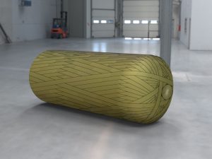
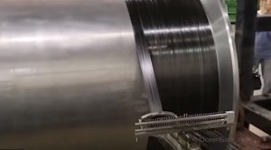 Titan fiber winding
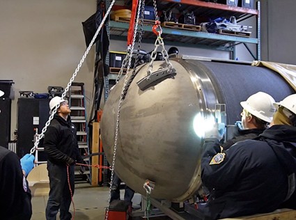 Titan hull
All other design elements that we are aware of raise the following critique:
- Carbon fiber winding method: Usually the filament winding method used for pressure vessels (such as gas bottles) applies “x-cross winding” due to the fact that tensions in the cylindrical area are multiple: hoop stress, axial stress, and radial stress. X-cross winding allows the management of all three stresses. In contrast, it is evident that OceanGate utilized the hoop winding method, which mainly withstands the hoop stress and no more.
 X-cross filament winding
- The joining of two different materials: this process has been touted as a high technological advance for which a Classification Registry would have not been able to assist, but the reality is very different. First of all, deformation against pressure of the two materials (titanium and carbon fiber) varies due to different flexibilities (Young module). This situation induces additional stress in the joint area. A similar problem can arise during temperature fluctuations. Consider temperatures ranging from 2°C at 4000 msw to 70°C under sunlight while the Titan is on a vessel deck. These pressure and temperature variations induce additional fatigue load on the pressure vessel resulting in deformation and modification of the materials’ tensile properties. All of which should have been considered.
- Carbon fiber is highly sensitive to local damage: Imagine a little scratch on the surface of the carbon fiber hull that cuts some wires. In that area the stress is higher due to a local reduction of the resistant material.
- In addition, the connection between carbon fiber and titanium (where the stresses are greater) should have been performed with an innovative technology called colamination. Instead, it seems that OceanGate joined the two materials with glue or through a similarly basic process. Such a large circumferential area was therefore prone to water seepage. Indeed, water seeping in at 380 bar has the ability to detach titanium and carbon fiber with catastrophic consequences.
- Other critical details emerge about a viewport rated for 1300 msw being used in a 3800 msw expedition, and a quantity of expired carbon fiber rejected by Boeing having been used for manufacturing the cylindrical hull.
- Being comprised of 3 different sections, made of different materials, likely the hull had little resistance to horizontal deflection, therefore preventing the installation of eye pads necessary to provide lifting in case of emergency on the seabed. It would have been impossible to install a single eye pad on the carbon fiber section; two eye pads on the titanium extremities would have generated upward deflection on the joints causing additional stress, intolerable when summed to the external pressure.
We could go on with other major and minor defects, but we assume this is enough to describe the amateurish design and manufacturing of Titan’s pressure hull.
The correct design approach
The correct design approach for a 3800 msw pressure capsule is to use a homogeneous material for the complete hull. This approach reduces conflicting performances of the section under pressure or differing temperature loads, minimizing the fatigue load on the entire structure. Moreover, with a metal pressure vessel, there are comprehensive and periodical integrity checks that include hydrotests, non-destructive tests on welds etc.
The weight of the cylindrical section could have been reduced by means of ribs or other reinforcing method. Titanium seems the logical material of choice in order to maintain a reasonable weight of the structure, also considering that the craft’s minimum volume should be increased to create space for the minimum safety equipment required by standard. These solutions are properly described in ASME or EN 13445 design codes.
OceanGate’s design process was instead more a “by-tentative” method without a proper engineering base. OceanGate tried incremental solutions and tested these on the field. Finally, they found a solution by using basic Finite Element Analysis (FEA) software which did not provide any element to assess fatigue of the materials and all the concurrent stress elements.
Lessons learned
It is sad to go through the available elements and note how many aspects had been overlooked and neglected, and the cost was five human lives.
In summary, there is a correct way to support subsea exploration: Considering safety as paramount, accepting evaluation by competent third parties and respecting the value of life of all those passionate about subsea exploration.
We will come back to other aspects of deep diving, in particular regarding the additional risk induced by Titan’s free diving method in place of the safer tethered approach.